Golden Mine Projects has nine operating mines in Australia, Peru, South Africa and West Africa (including the Asanko JV) and one project in Chile.
We have total attributable annual gold-equivalent production of 2.2Moz, attributable gold-equivalent Mineral Reserves of 52.1Moz and Mineral Resources of 116.0Moz.
Sustainability for Golden Mine Projects covers issues relating to our social licence to operate as well as mitigating the impact our operations have on the environment and adjacent communities
We continually look for people who have a high performance attitude and can grow with us.

Our operations depend upon the reliable supply of responsibly produced products and services, and the know-how of experts in their field.
SUSTAINABILITY ![]() Deposition techniques
Deposition techniques
Once the tailings slurry (either diluted or in a thicker paste form) reaches the designated tailings storage area, there are several options available for its deposition. These methods include spigotting, cyclone deposition, and the paddocking approach.
The paddock deposition method is typically suitable when dealing with fine-grained tailings characterized by a relatively narrow range of particle sizes. If the tailings consist of coarser materials covering a broader spectrum of particle sizes, spigotting may be a more appropriate choice. Cycloning is often employed in situations where spigotting would also be a viable option.
The primary objective of selecting a deposition method is to optimize the beaching process according to the specific characteristics of the tailings in question. For instance, if the tailings consist of fine and/or nearly uniform-sized particles, there will be minimal gravitational sorting along the beach, resulting in a limited beaching effect. Conversely, when dealing with tailings encompassing a wide range of particle sizes, the beaching process can generate a coarse outer layer with finer materials confined within the central part of the deposit, leading to varying permeabilities from the interior of the storage to its outer boundary.
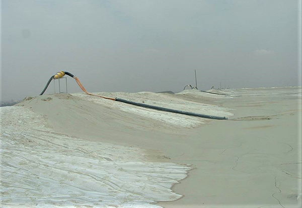
Spigots refer to multiple outlets positioned along a delivery pipeline. They are employed when it's feasible to create a natural separation between the coarser and finer fractions of tailings due to gravity.
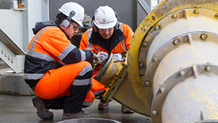
Within the tailings storage facility (TSF) embankment, a network of spigot pipes extends from delivery stations located on the pre-constructed embankment crest (refer to Figure 1a). These spigot pipes run along the primary wall, enabling deposition from various points along the crest. During a deposition cycle, a batch of adjacent spigots is opened to accommodate the slurry flow rate (as shown in Figure 1b). Spigots serve to break down the tailings delivery into smaller streams, leading to a reduction in stream velocity. This velocity reduction allows the coarser fractions to settle near the deposition point. As the beach area fills, spigots at one end of the batch are opened while an equivalent number at the opposite end is closed, causing the deposition to gradually progress along the spigot pipe and encircle the tailings dam.
A variation of this approach involves situating the spigot pipeline on the embankment crest, while the perimeter bund is raised to align with the tailings deposition cycle. These spigot lines typically incorporate a series of nozzles placed at intervals of 2 to 3 meters along the delivery pipeline. During each deposition cycle, a section of the spigot pipe is disassembled and shifted to the side, allowing for the raising of the perimeter bund, typically constructed using the beach tailings.
Figure 1a
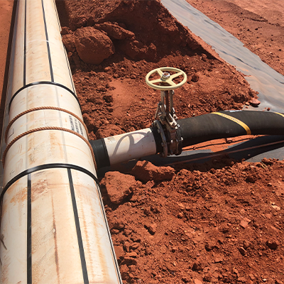
Figure 1b
Daywalls serve the purpose of creating vertical freeboard when achieving it through other means is not feasible. This situation arises under the following conditions:
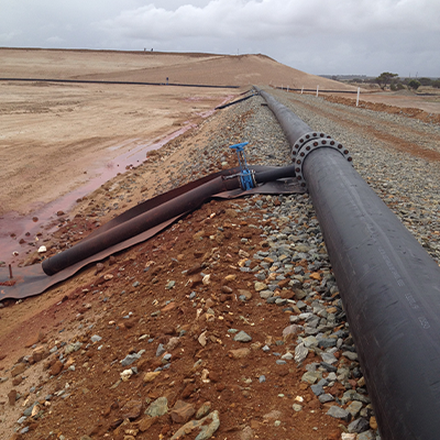
The term "daywall" comes from its usage during daylight hours when supervision is available and visibility is good. A conventional daywall is employed to deposit uniformly graded tailings through an open-ended discharge positioned at one end of the paddock daywall (see Figure 2).
The concept behind a paddock or daywall is to create small impoundments or containment berms using dried-out tailings borrowed from the previous layer, placed around the paddock's perimeter or edge (refer to Figure 3). These shallow paddocks are then filled with a dilute slurry (approximately 30-50% solids). Tailings solids settle out of suspension, releasing clear water, most of which can be drained from the paddock surface into the basin through a drain or "vent" pipe. The resulting layer of slimes continues to dry out, primarily through evaporation, resulting in surface shrinkage and cracking.
Since each subsequent layer is deposited on top of the previous one, a paddock or daywall can essentially only be developed in an upstream direction. By definition, the stability of the upstream wall development depends on the strength of the earlier deposited underlying layers. Therefore, it is crucial to construct a daywall facility in thin layers (maximum 200 mm) to allow for consolidation.
Figure 2
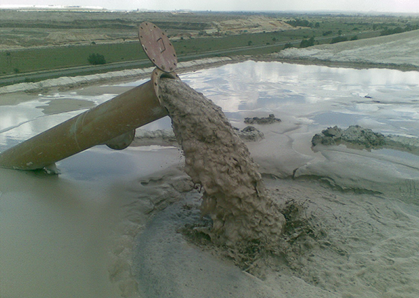
Figure 3
The operational principle of a cyclone is depicted in Figure 4. A cyclone is a specialized apparatus devoid of any moving components. It comprises a conical enclosure with an inlet pipe that enters the cone tangentially at its wider-circumference closed end. Another pipe enters the cone along its central axis and extends into the body of the cone. The slurry feed is introduced under pressure and compelled to swirl with a spiral motion towards the narrower end due to centrifugal forces. During this process, the larger particles in the slurry are driven downward and away from the central axis, moving toward the cone wall and the narrower cone exit. Conversely, the smaller particles concentrate along the axis of rotation and travel in the opposite direction, progressing towards the axial pipe known as the "vortex finder."
The end result is that the finer particles and a majority of the water exit the cyclone through the vortex finder, forming the "overflow," while the partially dewatered larger particles exit at the opposite end as the coarser "underflow" (refer to Figure 5).
Figure 4
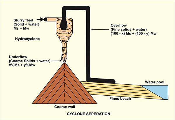
Figure 5
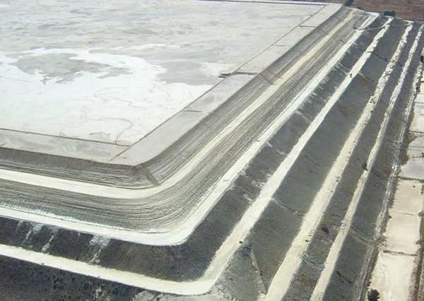
The primary purpose of employing a cyclone is to produce underflow material with enhanced geotechnical properties, including higher permeability, faster consolidation, and increased strength gain compared to the original tailings. This improved underflow can be used to construct a superior and/or quicker impoundment wall for the tailings storage facility (see Figure 6).
Utilizing cyclone-produced tailings in an embankment offers substantial benefits. Substituting cyclone-generated sand for natural soils or mine waste can result in significant cost savings due to the on-site production of sands, considerably reducing expenses associated with hauling and placing fill material. By extracting the sand fraction from the total tailings stream for use in the downstream embankment, the overall volume of tailings discharged into the basin is reduced. This reduction in impoundment storage requirements leads to lower embankment height, volume, and costs.
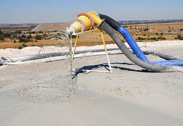
Cyclone underflow can also be generated off the embankment using a static cyclone station. These two fractions can be placed separately, typically through spigots and open ends.
With on-wall generation of underflow, the wall's construction can progress more rapidly, independent of the tailings' need for drying. A pressurized cyclone typically allocates 20% to 30% of the mass to underflow. The split can be adjusted but must satisfy two criteria: there must be enough underflow mass to construct the wall, and it must meet quality standards, particularly in terms of specific permeability to meet the wall's geotechnical strength requirements. Unfortunately, these two criteria are often in opposition, requiring an optimal balance between mass and quality.
On-wall cycloning aims to use underflow tailings to build an impoundment wall to contain the overflow. To ensure the stability of the storage facility, the underflow wall must adhere to specific dimensions. The tailings wall can be developed upstream, centerline, or downstream, but regardless, the underflow wall must conform to a prescribed geometry. This entails achieving a particular mass split through the cyclone to ensure there is always enough underflow to construct the wall ahead of the rising overflow contained in the dam's basin (see Figure 7).
Furthermore, the specified geometry of the wall must be achieved with the desired quality of underflow, primarily concerning grading and permeability. A critical aspect of the success of a cyclone dam lies in the differential permeability between the underflow and overflow tailings, especially for an upstream storage facility. The minimum desired differential is two orders of magnitude, implying that the phreatic surface will be controlled near the interface between the underflow and overflow tailings.
The cyclone's role is crucial in generating an underflow of sufficient quantity and quality to meet the design profile requirements.
Figure 6
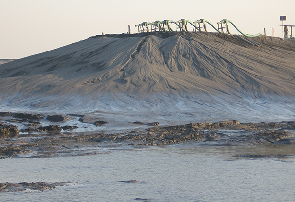
Figure 7
Single-point discharge is most commonly employed during flushing and maintenance campaigns and is not recommended for normal day-to-day operations. A single point discharge could also create in an uneven beach profile, which could lead to non-compliant supernatant pond placements.
Central Tailings Discharge (CTD) methods necessitate the use of thickened tailings. Thickening the tailings serves to reduce the water content within the tailings storage, facilitating the reclamation of more mine water. Recovering water through thickening is a more efficient process compared to directing it into an impoundment where it can be lost through evaporation, infiltration, and within the tailings voids.
When employing the CTD method for tailings deposition, the process involves radial discharge originating from a stationary central discharge tower or a specific number of spigots positioned within the central region of the Tailings Storage Facility (TSF). The discharge point(s) are incrementally elevated as the tailings' elevation increases. Typically, a circular paddock dam configuration is adopted and constructed (as depicted in Figure 8). The height of the perimeter embankments is contingent on the consistency of the tailings, the achieved beach angle, and the distance from the deposition point.
Figure 8
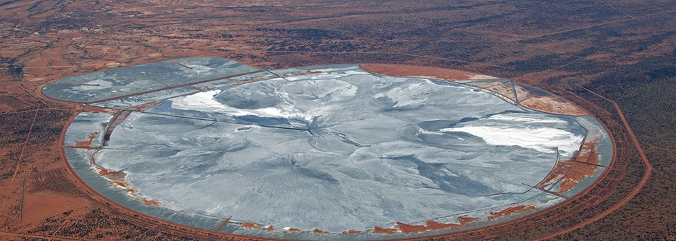
Compared to perimeter deposition methods, the heights of the perimeter embankments are minimized due to the conical shape of the tailings landform, with tailings sloping towards the outer perimeter. The initial site development typically includes relatively small containment embankments and an access spine or causeway extending from the perimeter to the central discharge point.
The CTD method is most suitable for beach slopes steeper than those achieved through conventional deposition approaches. A significant portion of tailings can be stored above the crest elevation of the perimeter embankments. In cases where the beaching profile is less steep than the design parameters, adjustments in either the footprint area or the height of the perimeter embankment become necessary to safely contain the same volume of tailings.
Deposition piping is typically required along the deposition causeway. Relocation of the piping is only necessary when the causeway and discharge point(s) are raised.
Tailings filtration can be accomplished through either pressure or vacuum methods. Common configurations for filtration plants include horizontally or vertically stacked drums, plates, and horizontal belts. While pressure filtration can be applied to a wider range of materials, vacuum belt filtration is often the more logical choice for larger-scale operations.
The nature of the tailings material plays a crucial role in filtration considerations. Tailings' particle size distribution is important, but so is its mineral composition. Particularly, a high concentration of clay minerals with particle sizes <74 µm, including the mineralogy of clay, tends to hinder effective filtration.
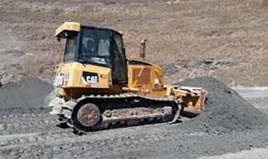
Filtered tailings are discharged from the processing facility within a specified range of moisture content. These tailings are then conveyed by either a conveyor system (as shown in Figure 9) or trucks, after which they are placed, spread, and compacted (as depicted in Figure 10). This process forms an unsaturated, dense, and stable tailings "stack" often referred to as a "dry stack." Importantly, these filtered tailings are not truly "dry" but rather unsaturated, thus correcting earlier terminology.
The predominant reasons for selecting dry-stacked filtered tailings as a management option are often related to water recovery for process water supply and terrain or foundation conditions that are unfavorable for conventional impoundments (Davies 2011). Water recovery is particularly crucial in arid regions where water is a precious resource and subject to regulations, as seen in places like Chile and Western Australia.
One of the primary advantages of dry stack tailings over other tailings management options is the ease of progressive reclamation and facility closure. These facilities can often be developed to initiate reclamation activities early in the project's life cycle. This approach offers several benefits, including better control of fugitive dust, the use of reclamation materials as they become available, and reduced short- and long-term environmental impacts. Progressive reclamation may involve constructing temporary covers and revegetating tailings slopes and surfaces as part of the annual operating cycle.
Filtered tailings can be placed in a relatively dense state, allowing for a higher concentration of solids per unit volume. Additionally, filtered tailings permit more efficient utilization of available land, such as valley slopes, and offer more flexibility in terms of foundation conditions compared to conventional impoundments.
Figure 9
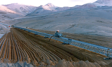
Figure 10